In lab 4, we learned about EEPOM and Servo motors. EEPROM is relevant to store longer-term medical data for interpretation even long after the use of a medical device (or after it is powered down). Learning about Servo motors opens doors to build motion-based medical devices, which are often necessary.
Part I: Getting Started with EEPROM
In this portion of the lab we were introduced to EEPROM. Typical data stored in the Arduino disappears when power is turned off, however, with the EEPROM, memory is stored and can be read back even after the device is powered down. This is illustrated in the below video. This is important as memory can be saved indefinitely, and data is no longer volatile.
This portion was a soft introduction to the concept. I wrote an array containing 6 numbers, wrote the data into the EEPROM, unplugged the Arduino, plugged it back in, and printed the array back on the Serial Monitor. EEPROM would destroy the onboard memory if simply put into an endless loop, so I had it nested inside of an if statement executed only when certain characters were typed into the Serial Monitor: ‘w’ for write and ‘r’ for read. Code, images, and video all below:


https://drive.google.com/file/d/1R-IQMeHa_SFKbSQ_C_QoJjIZxfKqMy8x/view?usp=sharing
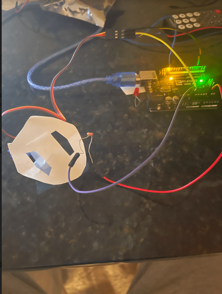
Part II: Build a Datalogger
Setup:

Code:

Output:

Part III: Servo
This portion of the lab introduced us to Servo and motion. In the first portion, I learned to make the Servo move. This was done by sending a high voltage pulse to the Servo, delaying for a short period of time, then sending a low pulse to the Servo followed by another delay.

Video: https://drive.google.com/file/d/17p9CEelz96Cwjhep-yRsVzEnHqnplsLs/view?usp=sharing
Next, we commanded the Servo to move to a certain angular position. I prompted users to enter the angle to the Serial Monitor and calculated the duration of the pulse accordingly, by normalizing it.

Video: https://drive.google.com/file/d/1_XvOQjjGz_BOeVHZ5iFVUMFD5ZRFQeop/view?usp=sharing
Next I wrote a script to make the Servo rotate between two positions. I did so by creating two functions, one representing each position. Code and video below:

Video:
https://drive.google.com/file/d/1Zdl3cGcwCVje3SKQUGppQwaBnfVS5eOW/view?usp=sharing
Next, I controlled the speed of the servo through the Serial Monitor. The speed
started as fast in the video below, and then I changed it to slow by changing
the delay time.

Video: https://drive.google.com/file/d/1QcXlC24lKIvjj2fQKu0y0ugiV_1vx7Lh/view?usp=sharing
Control w/ potentiometer
Next, I controlled the Servo through the potentiometer by setting the angle according to the value read by the potentiometer. I could similarly control through the potentiometer by setting the input PIN to analog and writing the voltage.

https://drive.google.com/file/d/1H7Z2jqdfctxzaeVTAEm_fmn8NgXT1sp6/view?usp=sharing
Angle and Speed
Next, I controlled the angle and speed of the potentiometer with the below code. I was able to parse both a number and character through the switch functionality. The user is easily able to understand the functionality, as it takes the format of one character and one number: ex f45 for fast 45º, s90 for slow 90º.

Finally, I attempted to position the Servo over a hole. I was able to link the Servo behavior to the potentiometer as per the code below. However, the mechanism I built couldn’t easily maneuver over the holes, perhaps due to weight. I was able to get the Servo to move or not move based on the readings of the potentiometer, but it struggled to move with the physical setup pictured below, despite multiple attempts.