In Lab 5, I worked on building a heartbeat sensor and integrating wireless communication with a remote and IR receiver. I started with initial code provided to us, which read optical signals from the KY-039 heartbeat sensor. This code delivered unfiltered values that I had to interpret to deliver a reliable, upgraded heartbeat sensor. This process is detailed below.
Part I:
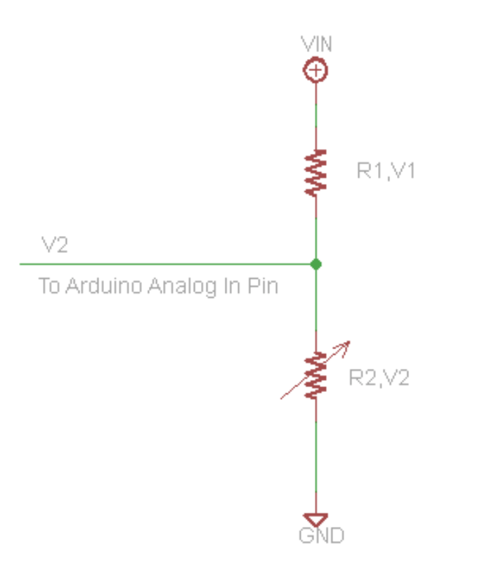
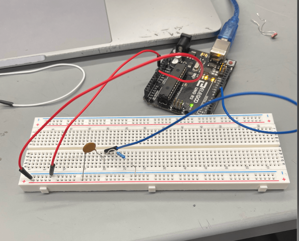
In the first portion of the lab, I began to make upgrades to the heartbeat sensor. First, I removed background noise by recording the initial value of the sensor in the setup portion of the code. I considered this as background noise and subtracted it from the calculation, providing a steady value of 0 when my finger wasn’t in the sensor. Next, I actually calculated the heartbeat and change in heartbeat and utilized the Kalman filter below. For the baseline value, I calculated my actual heartbeat at different rates and applied a ratio of the value to my heartbeat, as values were initially around 600 (although change in heartbeat was always accurate, and the more relevant portion of the device). I maintained consistency of lighting environment to mitigate the effects of any noise. If the device was subject to different environments, I would’ve built a cover around the actual filter to mitigate noise, but that was not necessary here.
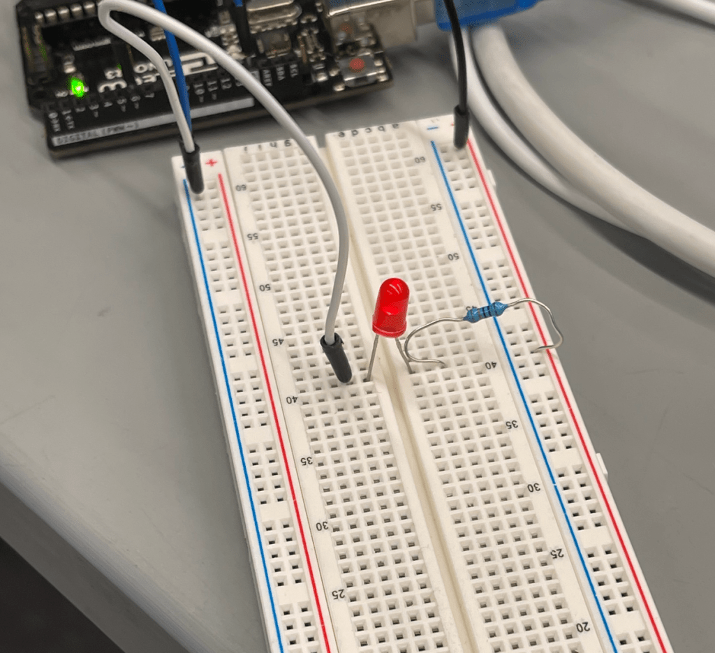
To improve the design of the heartbeat sensor, I also added an LED alarm that lit up if the heartbeat dropped below a certain threshold (50 BPM) or above a certain threshold (100 BPM). I would’ve used more extreme values, but wanted to ensure it was working properly. If I were to launch to market, these thresholds would change to 30 and 140, respectively. Additionally, if the heartbeat changed by more than 10BPM in between reads, the LED lit up. All of this functionality can be seen below.
Code:
#define HEART_PIN A5
#define DELAY_MS 10
double threshold;
static double oldValue = 0; //previous value
double alpha = 0.7; //filter coefficient was .7
double newValue;
double filterOutput;
double avg;
double change;
void setup() {
// put your setup code here, to run once:
pinMode(HEART_PIN, INPUT);
Serial.begin(9600);
newValue = analogRead(HEART_PIN);
if(newValue < 50){
threshold = newValue;
}
}
void loop() {
// put your main code here, to run repeatedly:
avg = 0;
// read new analog value
newValue = analogRead(HEART_PIN) – threshold;
//calculate weighted average
double filterOutput = alpha * oldValue + (1 – alpha) * newValue;
//output raw and filtered heart signal
//Serial.print(oldValue);
//Serial.print(“,”);
change = (filterOutput – oldValue);
Serial.println(.1 * filterOutput + change);
oldValue = filterOutput;
if((abs(change) > 10 || .1 * filterOutput + change > 100 || .1 * filterOutput + change < 50)){
digitalWrite(6, HIGH);
} else {
digitalWrite(6, LOW);
}
delay(DELAY_MS);
}
Video: https://drive.google.com/file/d/1A5Rbf4CL4K2DyE7ad5Vm3OFQjuBWR-gU/view?usp=sharing
Results:

Bluetooth Integration
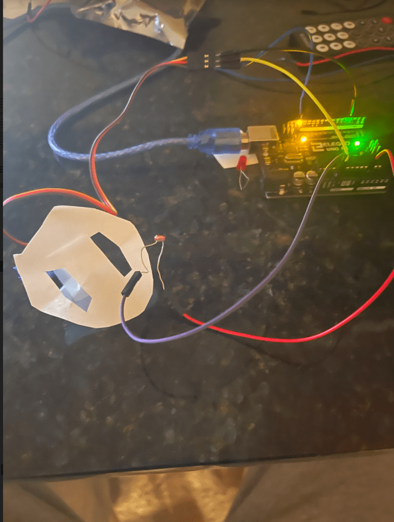
In the next portion of the lab I utilized Arduino’s IR Remote library to incorporate a remote control and bluetooth to upgrade the heartbeat monitor. The physical setup otherwise remained the same, except with the addition of this remote functionality. I added the following functionalities for four different remote buttons: 4 turned the LED on when it was off, 5 turned the LED off when it was on (i.e. silencing the alarm, until 4 was pressed again), 8 turned the readings off (set heartbeat to 0), and 2 turned the readings back on. All of this functionality is displayed in the below video. I was able to achieve these results by interpreting the hexadecimal outputs of the remote from the IR reader. Initially, the IR reader was giving different hexadecimal results for the same button, but that issue fortunately ending up resolving itself.
#include <IRremote.h>
#define HEART_PIN A5
#define DELAY_MS 10
double threshold;
static double oldValue = 0; //previous value
double alpha = 0.7; //filter coefficient was .7
double newValue;
double filterOutput;
double avg;
double change;
int RECV_PIN = 11;
int val = 1;
int pwr = 0;
unsigned long four = 0xFF10EF;
IRrecv irrecv(RECV_PIN);
decode_results results;
void setup() {
// put your setup code here, to run once:
pinMode(HEART_PIN, INPUT);
Serial.begin(9600);
newValue = analogRead(HEART_PIN);
if(newValue < 50){
threshold = newValue;
}
irrecv.enableIRIn();
}
void loop() {
// put your main code here, to run repeatedly:
avg = 0;
// read new analog value
newValue = analogRead(HEART_PIN) – threshold;
//calculate weighted average
double filterOutput = alpha * oldValue + (1 – alpha) * newValue;
//output raw and filtered heart signal
//Serial.print(oldValue);
//Serial.print(“,”);
change = (filterOutput – oldValue);
if(pwr == 0){
Serial.println(.1 * filterOutput + change);
} else {
Serial.println(0);
}
oldValue = filterOutput;
if(val == 1 && (abs(change) > 10 || .1 * filterOutput + change > 100 || .1 * filterOutput + change < 50)){
digitalWrite(6, HIGH);
} else {
digitalWrite(6, LOW);
}
if(irrecv.decode(&results)){
int resultsvalue = results.value;
if(String(results.value, HEX) == “ff10ef”){
//4
digitalWrite(6, HIGH);
irrecv.resume();
val = 1;
}else if(String(results.value, HEX) == “ff38c7”){
//5
digitalWrite(6, LOW);
val = 0;
irrecv.resume();
} else if(String(results.value, HEX) == “ff18e7”){
//2
pwr = 1;
irrecv.resume();
} else if(String(results.value, HEX) == “ff4ab5”){
// 8
pwr = 0;
irrecv.resume();
}
irrecv.resume();
}
delay(DELAY_MS);
}
Video:
https://drive.google.com/file/d/11PL7IvNzL4pYJfN4XYcbD-GrxRjrXbK2/view?usp=sharing
Output:

Physical Setup: