Abstract: The focus of this lab is on analog inputs and outputs, and more generally, on using a microcontroller to both generate and measure signals. There are multiple components focusing on signal generation, analog outputs, analog inputs, and a medical device project.
PART I: Signal Generation
The signal generation component consisted of three parts: writing a numerical ramp output, generating a sine wave on the serial plotter, and writing a program to generate two signals at once. Code and images are given below:
RAMP OUTPUT
int val = 4;
void setup() {
Serial.begin(9600);
}
void loop() {
Serial.println(val);
if(val < 20) {
val = val + 2;
} else {
val = 0;
}
delay(200);
}

SINE WAVE
void setup() {
Serial.begin(9600);
}
void loop() {
Serial.println(0);
Serial.println(.288);
Serial.println(.5);
Serial.println(.7071);
Serial.println(.866);
Serial.println(.9659);
Serial.println(1);
Serial.println(.9659);
Serial.println(.866);
Serial.println(.7071);
Serial.println(.5);
Serial.println(.288);
Serial.println(0);
Serial.println(-.288);
Serial.println(-.5);
Serial.println(-.7071);
Serial.println(-.866);
Serial.println(-.9659);
Serial.println(-1);
Serial.println(-.9659);
Serial.println(-.866);
Serial.println(-.7071);
Serial.println(-.5);
Serial.println(-.288);
}

TWO SIGNALS
nt val = 0;
int val2 = 0;
void setup() {
Serial.begin(9600);
}
void loop() {
if(val < 20) {
val = val + 2;
} else {
val = 0;
}
if(val2 < 50) {
val2 = val2 + 10;
} else {
val2 = -50;
}
Serial.println(val);
Serial.print(“,”);
Serial.println(val2);
}

PART II: Generating Sound
In this component of the lab we generated sound using the Arduino and a Piezzo buzzer. The task here was to make five sounds, the code and videos for which are given below:
Fast Sound:
https://drive.google.com/file/d/1ZkJ12g-ztMeo-hcLgRDit145VRIl6QDD/view?usp=sharing
FAST Sound:
void setup() {
Serial.begin(9600);
pinMode(7, OUTPUT);
}
void loop() {
tone(7, 1000, 2);
tone(7, 500, 2);
tone(7, 200, 2);
tone(7, 500, 2);
delay(200);
}
NO Sound:
https://drive.google.com/file/d/1NR98jWow7tEza5nXwWxU8EmQpeZ1t0IY/view?usp=sharing
void setup() {
Serial.begin(9600);
pinMode(7, OUTPUT);
}
void loop() {
tone(7, 1000, 500);
tone(7, 500, 2);
tone(7, 200, 2);
tone(7, 500, 2);
}
YES Sound:
https://drive.google.com/file/d/1wL5EfeN3hpdM6mBw-4AjwEbYYHf7h7in/view?usp=sharing
void setup() {
Serial.begin(9600);
pinMode(7, OUTPUT);
}
void loop() {
tone(7, 440);
delay(700);
tone(7, 660);
delay(700);
noTone(7);
delay(5000);
}
EMERGENCY Sound:
https://drive.google.com/file/d/1zxqiONZ_t1lPTD1GYRVzEz9zNTrSKarf/view?usp=sharing
void setup() {
Serial.begin(9600);
pinMode(7, OUTPUT);
}
void loop() {
tone(7, 770);
delay(700);
tone(7, 880);
delay(700);
tone(7, 480);
delay(700);
tone(7, 880);
noTone(7);
delay(5000);
}
SLOW Sound:
https://drive.google.com/file/d/1QB70gN0ABei9TnyPl-CuU38oKNghmsXN/view?usp=sharing
void setup() {
Serial.begin(9600);
pinMode(7, OUTPUT);
}
void loop() {
tone(7, 240);
delay(700);
tone(7, 120);
delay(700);
tone(7, 220);
delay(700);
}
All of these sounds could be used on a medical device as an indicator. Additionally, these videos show that the Arduino is capable of connection to the Oscilloscope.
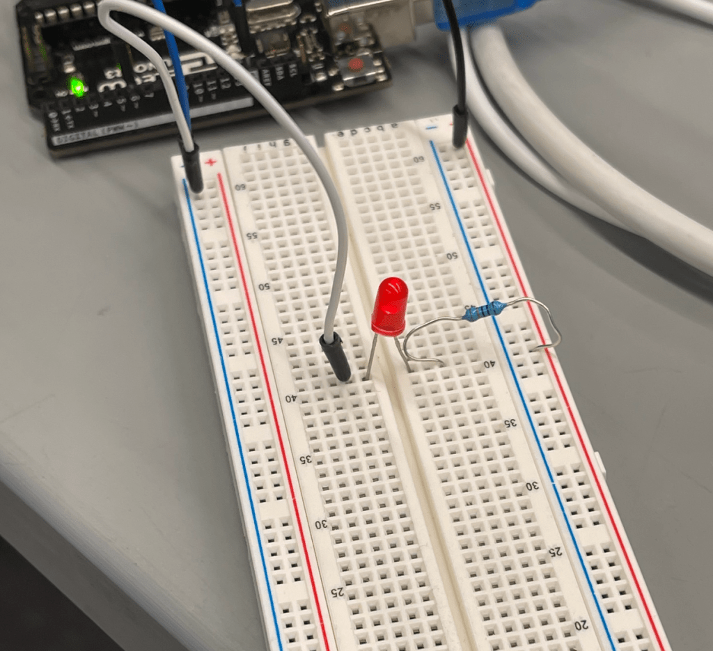
Part III: Controlling LED Brightness
The next portion of the lab covered controlling LED brightness and using Analog Inputs to control the LED. Find all code and some photos below:
LED Brightness (25%)
int brightness = 25;
void setup() {
Serial.begin(9600);
pinMode(7, OUTPUT);
}
void loop() {
digitalWrite(7, HIGH);
delay(brightness);
digitalWrite(7, LOW);
delay(100 – brightness);
}
LED Brightness (90%)
int brightness = 90;
void setup() {
Serial.begin(9600);
pinMode(7, OUTPUT);
}
void loop() {
digitalWrite(7, HIGH);
delay(brightness);
digitalWrite(7, LOW);
delay(100 – brightness);
}
ANALOG WRITE BRIGHTNESS (2)
int brightness = 2;
void setup() {
Serial.begin(9600);
pinMode(6, OUTPUT);
}
void loop() {
analogWrite(6, brightness);
}
ANALOG WRITE BRIGHTNESS (25)
int brightness = 25;
void setup() {
Serial.begin(9600);
pinMode(6, OUTPUT);
}
void loop() {
analogWrite(6, brightness);
}
ANALOG WRITE BRIGHTNESS (225)
int brightness = 255;
void setup() {
Serial.begin(9600);
pinMode(6, OUTPUT);
}
void loop() {
analogWrite(6, brightness);}

Analog Brightness (255)
Finally, for this portion of the lab, we did something fun with brightness control, so I made a siren – code and video below:
https://drive.google.com/file/d/1ph9eIf5TZX26X7ssyfmF7C0HnXmkDV_V/view?usp=sharing
int brightness = 255;
int LED_PIN = 6;
void setup() {
Serial.begin(9600);
pinMode(6, OUTPUT);
}
void loop() {
while(brightness > 0){
lowerBrightness();
}
delay(200);
brightness = 0;
while(brightness < 255){
raiseBrightness();
}
delay(200);
}
void raiseBrightness() {
analogWrite(LED_PIN, brightness);
brightness = brightness + 1;
delay(10);
}
void lowerBrightness() {
analogWrite(LED_PIN, brightness);
brightness = brightness – 1;
delay(10);
}
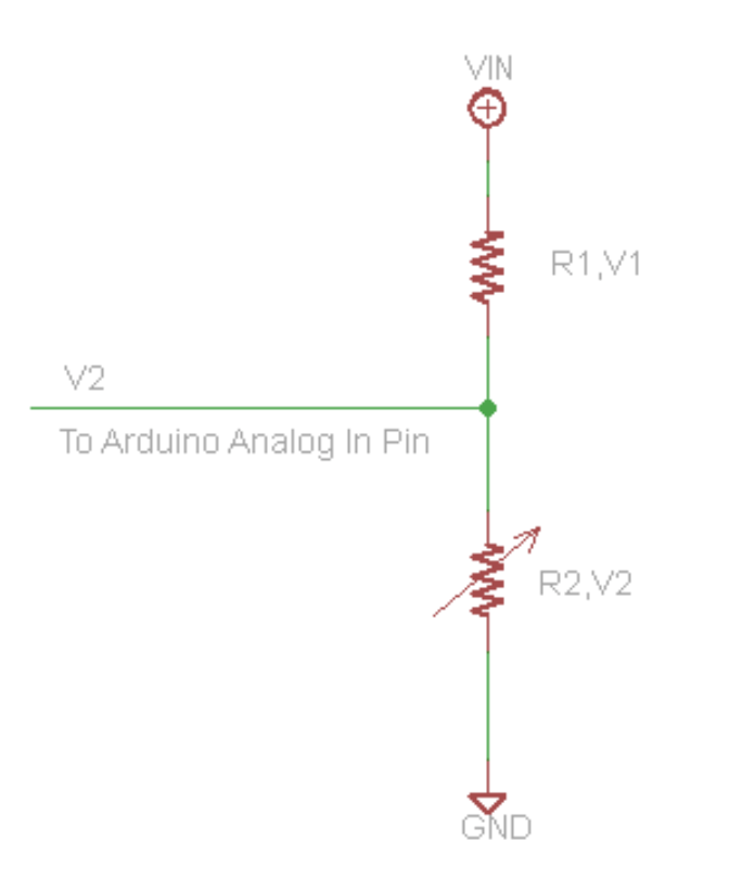
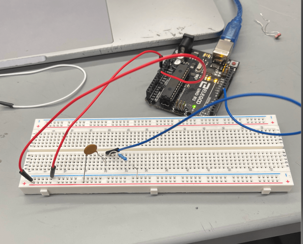
Section 4: Variable Resistance Sensor
In this section of the lab, we measured resistance using a photo-resistor, the voltage divider circuit, and analogRead(). Code, image and video below:
https://drive.google.com/file/d/1ph9eIf5TZX26X7ssyfmF7C0HnXmkDV_V/view?usp=sharing
Photoresistor:
void setup() {
Serial.begin(9600);
pinMode(2, INPUT);
}
void loop() {
int x = analogRead(2);
Serial.println(x);
}
Next, we used a capacitor to replicate the approach:
// RCtime — modified version
#define MAX_COUNT 400000 //define a macro (token: “MAX_COUNT”) (expression: “400,000”) to use later
int sensorPin = 4; // 220 or 1k resistor connected to this pin
long result = 0;
void setup() {
Serial.begin(9600);
Serial.println(“Testing RCtime”);
}
void loop() // run over and over again
{
Serial.println( RCtime(sensorPin) );
delay(10);
}
long RCtime(int sensorPin) {
long result = 0;
pinMode(sensorPin, OUTPUT); // make pin OUTPUT
digitalWrite(sensorPin, HIGH); // make pin HIGH to discharge capacitor – study the schematic
delay(1); // wait ~1ms to make sure cap is discharged
pinMode(sensorPin, INPUT); // turn pin into an input and time till pin goes low
digitalWrite(sensorPin, LOW); // turn pullups off – or it won’t work
while (digitalRead(sensorPin)) { // wait for pin to go low
result++;
if (result == MAX_COUNT) break; // don’t wait forever for pin to go low
// if result reaches the maximum value we defined earlier (400,000) stop waiting.
// this means that if RCtime returns 400,000, it really
// means that RCtime is >= 400,000.
// you can change this value of 400,000 to something else by changing the macro definition.
// there is nothing magic about the number, 400,000.
}
return result; // report
}
w/ potentiometer
int count = 0;
void setup() {
Serial.begin(9600);
pinMode(2, INPUT);
Serial.println(“Start!”);
}
void loop() {
millis();
while(millis() < 5000){
if(digitalRead(2) == 1){

  count = count + 1;

  while(digitalRead(2) == 1){

    continue;

  }

}
}
Serial.print(count/5.0);
Serial.println(” steps taken per second!”);
delay(5000);
count = 0;
}

Output
Part IV:
Finally, we created a medical device to see how fast one could press a button:
int count = 0;
void setup() {
Serial.begin(9600);
pinMode(2, INPUT);
Serial.println(“Start!”);
}
void loop() {
millis();
while(millis() < 5000){
if(digitalRead(2) == 1){
count = count + 1;
while(digitalRead(2) == 1){
continue;
}
}
}
Serial.print(count/5.0);
Serial.println(” steps taken per second!”);
delay(5000);
count = 0;
}
